6.8. Communication and Control of Actuators#
To make actuators perform useful work, a microcontroller must communicate commands to them and control how much power they receive. This can be done in several ways, depending on the type of actuator and how much precision or power is needed. Most actuators are controlled using one of three methods: voltages, pulse-width modulation (PWM), or digital communication buses.
6.8.1. Voltage Control#
The simplest way to control an actuator is to apply a direct voltage across it. For example DC motors spin faster as the voltage increases.
There are two types of voltage control actuators:
Direct-drive actuators where the voltage/current directly powers the actuator
Signal-controlled actuators, where the voltage is just a control signal to an integrated driver circuit that actually delivers the power internally.
Microcontrollers can’t supply much current directly from their pins, so direct-drive actuators are usually driven through transistors or dedicated motor driver boards (e.g. h-bridge driver) that can handle higher power.
Voltage control is the simplest and cheapest because the required hardware is relatively inexpensive. However it does require a DAC output on the microcontroller pin.
6.8.2. PWM Control#
Pulse Width Modulation (PWM) is a technique where a digital signal rapidly switches between ON and OFF, but the ratio of ON-time to OFF-time (the duty cycle) carries information. Even though PWM is made of only two states (0 and 1), varying the duty cycle allows it to represent a continuous range of values, much like an analog signal.
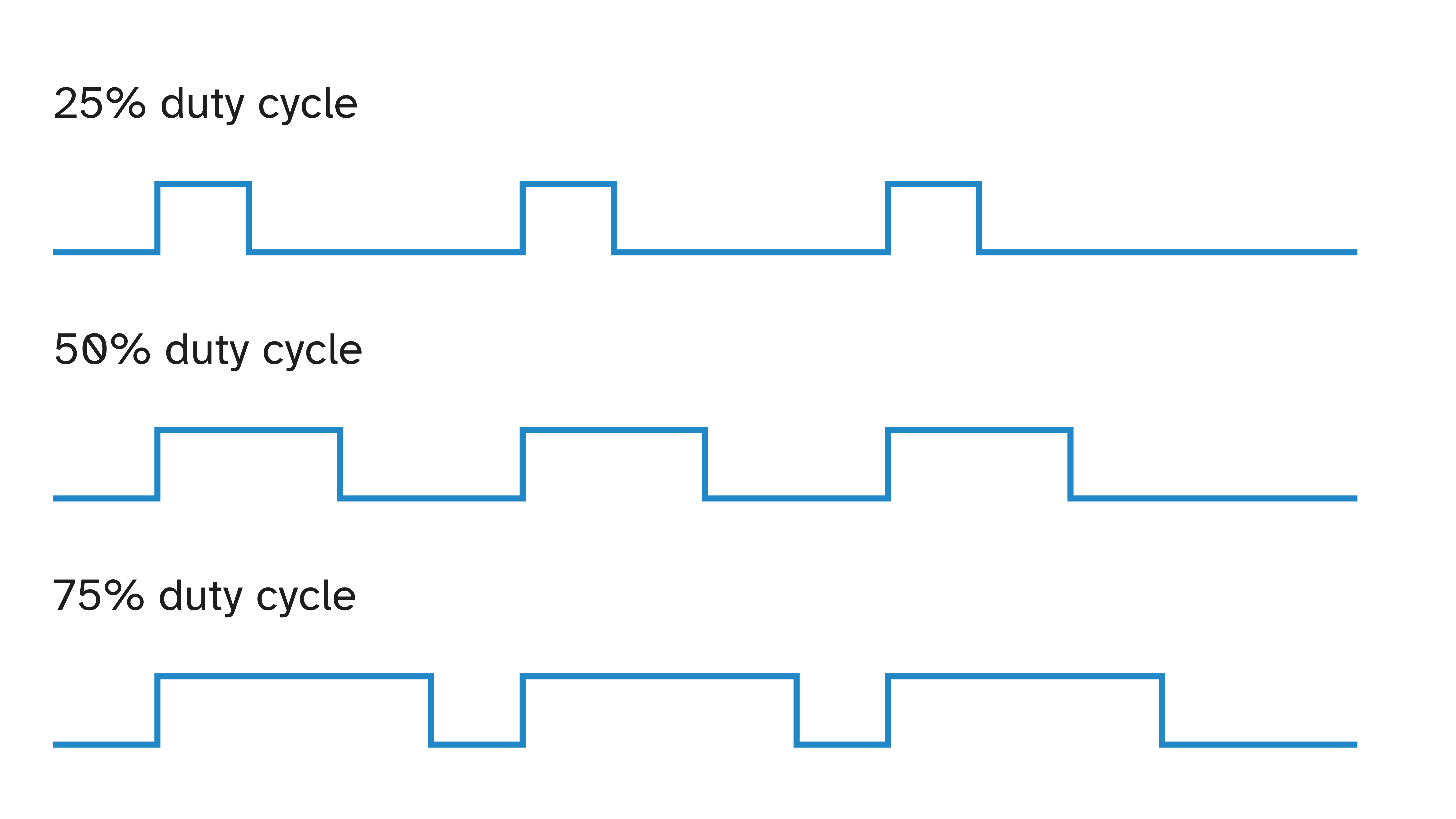
PWM signals are generated by microcontrollers at high frequencies (hundreds or thousands of times per second). To an electrical circuit or actuator, this repeated pulsing “averages out” into a smooth effect. For example, an LED driven with 50% duty cycle appears half as bright, even though it is actually turning fully on and off rapidly.
Because PWM only requires on/off signals, it’s robust to noise and can be sent reliably over longer distances. It also doesn’t require expensive analogue hardware, making it ideal for small embedded systems.
6.8.3. Digital Bus Control#
More complex actuators have built-in electronics and communicate using digital bus protocols like I2C, SPI, 1-Wire, or CAN bus.
Instead of just sending voltages or duty cycles, the microcontroller sends data packets that include commands (like “move to 90°” or “set speed to 50 RPM”) and receives feedback (like position, current draw, or error codes).
This approach is used in:
Smart servos with built-in position feedback
Motor controllers that regulate torque and speed
Electro-pneumatic valves that report their status
Stepper drivers that handle timing and current control internally
Digital buses allow many actuators to share just a few wires, which reduces wiring complexity and lets the controller coordinate many actuators at once.